Creation & Validation
Intuitive tools for easy, standard-compliant creation and editing of IODD files – ensuring your device descriptions are always up-to-date and compliant.

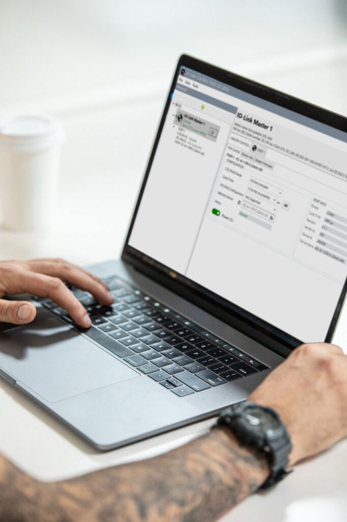
Control & Analysis
User-friendly software for direct control, analysis, and monitoring of IO-Link devices during development.

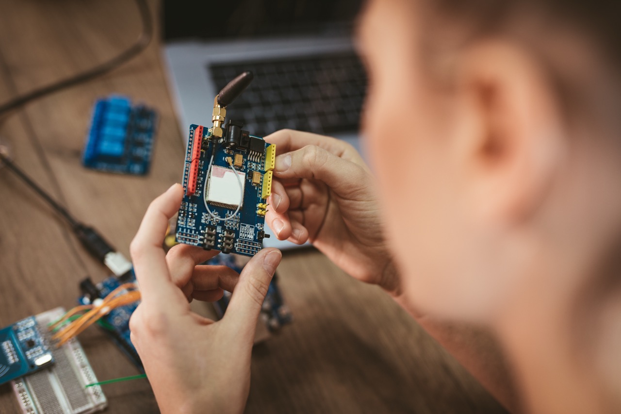
Emulation & Prototyping
Flexible emulators and prototyping solutions that allow you to test and realistically simulate your IO-Link devices early on.