

Startseite » Products » Test device for EMC compliance testing
Test device for EMC compliance testing
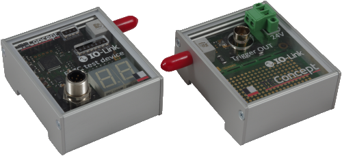
The IO-Link Interface Specification V1.1.X requires a specific test device for EMC testing (see Appendix H.2.2: Test of a Master), which is to be connected to the master when performing the EMC test.
Functional Description
For the test, the test device generates 8-bit random numbers, which are read as process data by the master and should be written back to the test device in the next cycle.
The device then checks whether the process data sent back by the master matches the data sent in the previous cycle and increments an internal error counter if this is not the case. The error counter is also incremented if a checksum error or a parity error is detected, or if a master cycle is completely missing.
The status of the error counter is shown on a seven-segment display. Additionally, the master can read the error counter via IO-Link parameters after the test is completed. The IO-Link interface also allows the error levels of the individual error types to be read.
To better identify problems, there is an optical trigger output that can be connected to a trigger box via a fiber optic cable. The trigger box converts the optical signal into an electrical signal, which can then be connected, for example, to the trigger input of a storage oscilloscope.
The EMC test device is configurable. For example, the baud rate can be set via DIP switches.
EMC Test Device Properties
- Complies with the requirements of the V1.1.X IO-Link Interface Specification
- All 3 COM rates are supported (DIP switches and IO-Link parameters)
- Internal pseudo-random number generator
- Error counters for parity, checksum, data, and timeout errors
- Dual 7-segment display for operating mode and error status
- Error levels are accessible via IO-Link
- Additional support for round-trip delay measurements
- Total error count and maximum error count within a standardized group of M-sequences available separately via IO-Link. Two group sizes selectable per COM speed
Contact

- +49 761 21443640
- +49 761 21443636
- info@teconcept.de
If you have any questions about the test device for EMC compliance testing or its functions, please use our contact form. Our team will be happy to assist you.